Search This Blog

Wednesday, 8 May 2024

(PART-2) Writing our Video Driver in C Kernel for our OS


Cover image for Writing My Own VGA Driver 

Why a VGA Driver?

Our operating system needs some way to interact with the user. This requires us to do some form of I/O. First, we want to focus on visual output. We will rely on the VGA 80x25 text video mode as it is very convenient to handle and flexible enough for basic terminal functionality. This is the same mode that was already used by the BIOS while booting our kernel.

With VGA we can produce screen output by modifying a dedicated memory region, called the video memory, directly. In addition to that, there are specific port addresses that we can use to interact with device ports using the port I/O CPU instructions in and out. This is possible because all I/O ports (including the VGA ports) are mapped to specific memory locations.

The task of our VGA driver will be to encapsulate these low level memory manipulations within higher level functions. Instead of issuing individual CPU instructions and modifying memory addresses we want to be able invoke a function to print a string on the screen or clear all output. In this post we are going to write such a minimal VGA driver.

The remainder of the article is structured as follows. The next section explains how we can interface with I/O ports using C. Afterwards we will put this knowledge to use and implement functions to retrieve and set the text cursor position. Then we will write code to print individual characters on the screen by writing to the video memory. We will combine the cursor manipulation with the character printing to provide functionality for printing strings to the screen. The sections after that focus on a few extensions such as handling newline characters, scrolling, as well as clearing the screen. The final section adjusts the main kernel function to make use of our newly written driver.

The source code is available on GitHub.

Interfacing with I/O Ports from C

One important part of I/O drivers is be the ability to interface with I/O devices through ports. In our VGA driver we only need to access the ports 0x3d4 and 0x3d5 for now, in order to read and set the cursor position while in text mode.

As mentioned earlier, we can utilize the in and out instructions to read and write port data, respectively. But how do we make use of those instructions from within C?

Luckily, the C compiler supports inline assembler code by calling the __asm__ function that lets us write assembler code, passing C variables as input and writing results back into C variables. The assembler instruction, the output parameters, and the input parameters of the __asm__ function are separated by :. The syntax is a bit different compared to NASM, e.g. the order of the instruction operands is reversed.

Let's take a look at the following two functions to read/write data from/to a specified port.

unsigned char port_byte_in(unsigned short port) {
    unsigned char result;
    __asm__("in %%dx, %%al" : "=a" (result) : "d" (port));
    return result;
}

void port_byte_out(unsigned short port, unsigned char data) {
    __asm__("out %%al, %%dx" : : "a" (data), "d" (port));
}

For our port_byte_in function we map the C variable port into the dx register, execute in al, dx, and then store the value of the al register into the C variable result. The port_byte_out function looks similar. It executes out dx, al, mapping the port to dx and the data to al. As we are only writing data there are no output parameters and the function has no return value.

Getting and Setting the Cursor Position

With our newly written port I/O functions we are ready to interact with the VGA text mode cursor. In order to read or change the cursor position we need to modify the VGA control register 0x3d4 and read from or write to the respective data register 0x3d5.

The 16 bit cursor position is encoded as 2 individual bytes, the high and the low byte. The data register will hold the low byte if the control register is set to 0x0f, and the high byte if the value 0x0e is used. First we will define the register addresses and the codes for our offset as C constants.

#define VGA_CTRL_REGISTER 0x3d4
#define VGA_DATA_REGISTER 0x3d5
#define VGA_OFFSET_LOW 0x0f
#define VGA_OFFSET_HIGH 0x0e

We are going to represent our cursor offset as the video memory offset. The memory offset is twice the cursor offset, because each position in the text grid is represented by 2 bytes, one for the character and one for color information.

As we cannot fit a memory offset having twice the size of a 16 bit cursor offset into a 16 bit short, we will use a 32 bit integer. And now we can write a set_cursor and a get_cursor function that takes our internal cursor offset.

void set_cursor(int offset) {
    offset /= 2;
    port_byte_out(VGA_CTRL_REGISTER, VGA_OFFSET_HIGH);
    port_byte_out(VGA_DATA_REGISTER, (unsigned char) (offset >> 8));
    port_byte_out(VGA_CTRL_REGISTER, VGA_OFFSET_LOW);
    port_byte_out(VGA_DATA_REGISTER, (unsigned char) (offset & 0xff));
}

int get_cursor() {
    port_byte_out(VGA_CTRL_REGISTER, VGA_OFFSET_HIGH);
    int offset = port_byte_in(VGA_DATA_REGISTER) << 8;
    port_byte_out(VGA_CTRL_REGISTER, VGA_OFFSET_LOW);
    offset += port_byte_in(VGA_DATA_REGISTER);
    return offset * 2;
}

Note that because our memory offset is double the cursor offset, we have to map the two offsets by multiplying or dividing by 2. We also have to do some bit shifting / masking in order to retrieve the high and the low byte from our integer.

Printing a Character on Screen

Having the cursor manipulations in place, we also need to be able to print characters at a specified position on screen. We already did that in our dummy kernel in the previous post. So let's take that code and make it a bit more generic. First, we will define a few helpful constants containing the starting address for the video memory, the text grid dimensions, as well as a default coloring scheme to use for our characters.

#define VIDEO_ADDRESS 0xb8000
#define MAX_ROWS 25
#define MAX_COLS 80
#define WHITE_ON_BLACK 0x0f

Next, let's write a function to print a character on screen by writing it to the video memory at a given memory offset. We are not going to support different colors for now but we can adjust this later if needed.

void set_char_at_video_memory(char character, int offset) {
    unsigned char *vidmem = (unsigned char *) VIDEO_ADDRESS;
    vidmem[offset] = character;
    vidmem[offset + 1] = WHITE_ON_BLACK;
}

Now that we can print characters on screen and modify the cursor, we can implement a function that prints a string and moves the cursor accordingly.

Printing Text and Moving the Cursor

In C a string is a 0-byte terminated sequence of ASCII encoded bytes. To print a string on the screen we need to:

  1. Get the current cursor offset.
  2. Loop through the bytes of the string, writing them to the video memory, incrementing the offset.
  3. Update the cursor position.

Here goes the code:

void print_string(char *string) {
    int offset = get_cursor();
    int i = 0;
    while (string[i] != 0) {
        set_char_at_video_memory(string[i], offset);
        i++;
        offset += 2;
    }
    set_cursor(offset);
}

Note that this code does neither handle newline characters, nor offsets that are out of bounds at this point. We can fix that by implementing scrolling functionality in case of our offset growing out of bounds, and moving the cursor to the next line when we detect a newline character. Let's look into handling newline characters next.

Handling Newline Characters

A newline character is actually a non-printable character. It does not take space in the grid but instead moves the cursor to the next line. To do that we will write a function that takes a given cursor offset and computes the new offset, which is the first column in the next row.

Before we implement that we will write two small helper functions. get_row_from_offset takes a memory offset and returns the row number of the corresponding cell. get_offset returns a memory offset for a given cell.

int get_row_from_offset(int offset) {
    return offset / (2 * MAX_COLS);
}

int get_offset(int col, int row) {
    return 2 * (row * MAX_COLS + col);
}

Combining those two functions we can easily write the function that moves the offset to the next line.

int move_offset_to_new_line(int offset) {
    return get_offset(0, get_row_from_offset(offset) + 1);
}

With this function at our disposal we can modify the print_string function to handle \n.

void print_string(char *string) {
    int offset = get_cursor();
    int i = 0;
    while (string[i] != 0) {
        if (string[i] == '\n') {
            offset = move_offset_to_new_line(offset);
        } else {
            set_char_at_video_memory(string[i], offset);
            offset += 2;
        }
        i++;
    }
    set_cursor(offset);
}

Next, let's look at how we can implement scrolling.

Scrolling

As soon as the cursor offset exceeds the maximum value of 25x80x2 = 4000 the terminal output should scroll down. Without a scroll buffer the top line will be lost but this is ok for now. We can implement scrolling by executing the following steps:

  1. Move all rows but the first one by 1 row upwards. We do not need to move the top row as it would be out of bounds anyway.
  2. Fill the last row with blanks.
  3. Correct offset to be inside our grid bounds again.

The following animation illustrates the scrolling algorithm.

We can implement the row movement by copying a chunk of the video memory. First, we will write a function that copies a given number of bytes nbytes in memory from *source to *dest.

void memory_copy(char *source, char *dest, int nbytes) {
    int i;
    for (i = 0; i < nbytes; i++) {
        *(dest + i) = *(source + i);
    }
}

With the memory_copy function at our disposal we can implement a scrolling helper function that takes a given offset, copies the desired memory region, clears the last row, and adjusts the offset to be inside the grid bounds again. We will use the get_offset helper method to conveniently determine the offset for a given cell.

int scroll_ln(int offset) {
    memory_copy(
            (char *) (get_offset(0, 1) + VIDEO_ADDRESS),
            (char *) (get_offset(0, 0) + VIDEO_ADDRESS),
            MAX_COLS * (MAX_ROWS - 1) * 2
    );

    for (int col = 0; col < MAX_COLS; col++) {
        set_char_at_video_memory(' ', get_offset(col, MAX_ROWS - 1));
    }

    return offset - 2 * MAX_COLS;
}

Now we only need to modify our print_string function so that each loop iteration it checks if the current offset exceeds the maximum value and scroll if needed. This is the final version of the function:

void print_string(char *string) {
    int offset = get_cursor();
    int i = 0;
    while (string[i] != 0) {
        if (offset >= MAX_ROWS * MAX_COLS * 2) {
            offset = scroll_ln(offset);
        }
        if (string[i] == '\n') {
            offset = move_offset_to_new_line(offset);
        } else {
            set_char_at_video_memory(string[i], offset);
            offset += 2;
        }
        i++;
    }
    set_cursor(offset);
}

Clearing the Screen

After the our kernel has started, the video memory will be filled with some information from the BIOS that is no longer relevant. So we need a way to clear the screen. Fortunately this function is easy to implement given our existing helper functions.

void clear_screen() {
    for (int i = 0; i < MAX_COLS * MAX_ROWS; ++i) {
        set_char_at_video_memory(' ', i * 2);
    }
    set_cursor(get_offset(0, 0));
}

Hello World and Scrolling in Action

We can adjust our main function to print a string now! We only need to include the display header file so our compiler knows that the driver functions exist.

#include "../drivers/display.h"

void main() {
    clear_screen();
    print_string("Hello World!\n");
}

To visualize the scrolling I wrote an extended main function that prints increasing characters, launched QEMU in debug mode, attached the GNU debugger (gdb), put a breakpoint in the print function and executed the following debug instruction to slow down the scrolling so it becomes visible.

while (1)
shell sleep 0.2
continue
end

And this is the result:

scrolling in action

Horray! We managed to write a simple, yet working video driver that allows us to print strings on the screen. It even supports scrolling! Next up: Keyboard input :)


(PART-4) Writing our own SHELL like MS-DOS


Cover image for Writing My Own Shell 

Introduction

Operating systems provide high level functionality to interact with the computer hardware. This functionality needs to be made available to the user in some way, e.g. by a layer around the kernel, exposing simple commands. This outer layer is typically called a "shell".

As we only have a very simple text based VGA driver we will write a command-line shell. Graphical shells are beyond the scope of this series. The remainder of the post is structured as follows.

First, we will implement a key buffer that stores the user input and modify our keyboard callback to fill the buffer in addition to printing on screen. Next, we are going to add backspace functionality so we can correct typos. Thirdly, we will implement a very simple command parsing when the enter key is pressed. Finally, we modify our kernel entry to display a prompt after all initialization work is done.

Key Buffer

Our shell should support complex commands potentially having subcommands and arguments. This means having single key commands is not going to get us very far but we would rather have the user type commands consisting of multiple characters. We need a place to store the command as it is being typed, however. This is where the key buffer comes in.

We can implement the key buffer as an array of characters. It will be initialized with 0 bytes and key presses will be recorded from index 0 upwards. Inspecting this data structure a bit closer you will notice that this is just how we encoded strings. A series of characters, terminated by a 0 byte.

To work with the key buffer efficiently we need two more string utility functions: A function to calculate the length of a string and a function to append a character to a given string. The latter function is going to make use of the former.

int string_length(char s[]) {
    int i = 0;
    while (s[i] != '\0') {
        ++i;
    }
    return i;
}

void append(char s[], char n) {
    int len = string_length(s);
    s[len] = n;
    s[len + 1] = '\0';
}

Next, we can make a few adjustments to our keyboard callback function from the previous post. First, we want to get rid of the humongous switch statement and replace it by an array lookup based on the scan code. Secondly, we ignore all key up and non-alphanumeric scan codes. Lastly, we record each key in the key buffer and output it to the screen.

#define SC_MAX 57

static char key_buffer[256];

const char scancode_to_char[] = {
  '?', '?', '1', '2', '3', '4', '5',
  '6', '7', '8', '9', '0', '-', '=',
  '?', '?', 'Q', 'W', 'E', 'R', 'T',
  'Y', 'U', 'I', 'O', 'P', '[', ']',
  '?', '?', 'A', 'S', 'D', 'F', 'G',
  'H', 'J', 'K', 'L', ';', '\', '`',
  '?', '\\', 'Z', 'X', 'C', 'V', 'B',
  'N', 'M', ',', '.', '/', '?', '?',
  '?', ' '
};

static void keyboard_callback(registers_t *regs) {
    uint8_t scancode = port_byte_in(0x60);

    if (scancode > SC_MAX) return;

    char letter = scancode_to_char[(int) scancode];
    append(key_buffer, letter);
    char str[2] = {letter, '\0'};
    print_string(str);
}

This method works but it has two problems. First, it does not check the boundaries of the key buffer before appending, risking a buffer overflow. Secondly, it does not leave any room for mistakes when typing a command. We will leave fixing the buffer overflow to the reader and implement backspace functionality next.

Backspace

The user should be able to correct typos by pressing backspace, effectively deleting the last character from the buffer and from the screen.

Implementing the buffer modification can be done by reversing the append function. We simply set the last non-0 byte in the buffer to 0. The method will return true if we successfully removed an element from the buffer and false otherwise. Note that you have to import the type definition for bool using #include <stdbool.h>.

bool backspace(char buffer[]) {
    int len = string_length(buffer);
    if (len > 0) {
        buffer[len - 1] = '\0';
        return true;
    } else {
        return false;
    }
}

Printing a backspace character on screen can be implemented by printing an empty character at the position right before the current cursor position and moving the cursor backwards. We will make use of our get_cursor, set_cursor, and set_char_at_video_memory functions from the VGA driver.

void print_backspace() {
    int newCursor = get_cursor() - 2;
    set_char_at_video_memory(' ', newCursor);
    set_cursor(newCursor);
}

To complete the backspace functionality we modify the keyboard callback function by adding a branch specifically for backspace key presses. When backspace is pressed, we first attempt to delete the last character from the key buffer. If this was successful, we also show the backspace on screen. It is important to perform this check because otherwise the user would be able to backspace all the way through the screen without being stopped by prompts.

#define BACKSPACE 0x0E

static void keyboard_callback(registers_t *regs) {
    uint8_t scancode = port_byte_in(0x60);
    if (scancode > SC_MAX) return;

    if (scancode == BACKSPACE) {
        if (backspace(key_buffer)) {
            print_backspace();
        }
    } else {
        char letter = scancode_to_char[(int) scancode];
        append(key_buffer, letter);
        char str[2] = {letter, '\0'};
        print_string(str);
    }
}

Having a key buffer and backspace functionality in place, we can move to the last step: parsing and executing commands.

Parsing and Executing Commands

Whenever the user hits the enter key, we want to execute the given command. That typically involves parsing the command first, potentially splitting it into multiple subcommands, parsing arguments or invoking external functionality. For the sake of simplicity we will only implement very basic "parsing" that checks whether the string is a known command and if it is not, shows an error.

First, we need to write a function to compare two strings. It will go through both strings step by step, comparing the character values. Here goes the code.

int compare_string(char s1[], char s2[]) {
    int i;
    for (i = 0; s1[i] == s2[i]; i++) {
        if (s1[i] == '\0') return 0;
    }
    return s1[i] - s2[i];
}

Next, we have to implement a function execute_command that executes a given command. Our first version of the shell will only recognize a single command called EXIT that halts the CPU. Later we can implement other commands such as rebooting or interacting with a file system. If the command is unknown, we print an error message. Finally, we print a new prompt.

void execute_command(char *input) {
    if (compare_string(input, "EXIT") == 0) {
        print_string("Stopping the CPU. Bye!\n");
        asm volatile("hlt");
    }
    print_string("Unknown command: ");
    print_string(input);
    print_string("\n> ");
}

Finally, we adjust the keyboard callback to move the cursor to the next line, invoke execute_command, and reset the key buffer when the enter key is pressed.

#define ENTER 0x1C

static void keyboard_callback(registers_t *regs) {
    uint8_t scancode = port_byte_in(0x60);
    if (scancode > SC_MAX) return;

    if (scancode == BACKSPACE) {
        if (backspace(key_buffer) == true) {
            print_backspace();
        }
    } else if (scancode == ENTER) {
        print_nl();
        execute_command(key_buffer);
        key_buffer[0] = '\0';
    } else {
        char letter = scancode_to_char[(int) scancode];
        append(key_buffer, letter);
        char str[2] = {letter, '\0'};
        print_string(str);
    }
}

We are almost done! Let's update the main kernel function.

Updated Kernel Function

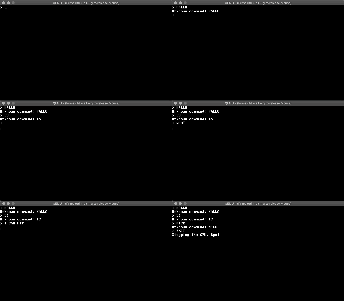
Actually, there is not much to do. We will clear the screen and display the initial prompt after all initialization work is done and that's it! The updated keyboard handler will do the rest. Here comes the code and a demo!

void start_kernel() {
    clear_screen();
    print_string("Installing interrupt service routines (ISRs).\n");
    isr_install();

    print_string("Enabling external interrupts.\n");
    asm volatile("sti");

    print_string("Initializing keyboard (IRQ 1).\n");
    init_keyboard();

    clear_screen();
    print_string("> ");
}

shell demo

Amazing, although not very practical until we add new commands :D. In the next post we will add dynamic memory allocation.


(PART-3) Writing our own KEYBOARD DRIVER for our OS


Cover image for Writing My Own Keyboard Driver 
 

Introduction

In the previous post we implemented a video driver so that we are able to print text on the screen. For an operating system to be useful to the user however, we also want them to be able to input commands. Text input and output will be the foundation for future shell functionality.

But how does the communication between the keyboard and our operating system work? The keyboard is connected to the computer through a physical port (e.g. serial, PS/2, USB). In case of PS/2 the data is received by a microcontroller which is located on the motherboard. When a key is pressed, the microcontroller stores the relevant information inside the I/O port 0x60 and sends an interrupt request IRQ 1 to the programmable interrupt controller (PIC).

The PIC then interrupts the CPU with a predefined interrupt number based on the external IRQ. On receiving the interrupt, the CPU will consult the interrupt descriptor table (IDT) to look up the respective interrupt handler it should invoke. After the handler has completed its task, the CPU will resume regular execution from before the interrupt.

For the complete chain to work we need to do some preparations during the kernel initialization. First, we have to setup the correct mapping inside the PIC so that our IRQs get translated to actual interrupts correctly. Then, we must create and load a valid IDT that contains a reference to our keyboard handler. The handler then reads all relevant data from the respective I/O ports and converts it to text that we can show to the user, such as LCTRL or A.

Now that we know the high level overview of what we need to do, let's jump into it! The remainder of this post is structured as follows. The next section focuses on defining and loading the IDT. Afterwards we will implement the keyboard interrupt handler and register it. Last but not least we extend the kernel functionality to execute the newly written code in the correct order.

The source code is available at GitHub. The code examples of this post use type aliases from #include <stdint.h> which are a bit more structured than the original C types. uint16_t corresponds to an unsigned 2 byte (16 bit) value, for example.

Setting Up The IDT

IDT Structure

The IDT consists of 256 descriptor entries, called gates. Each of those gates is 8 bytes long and corresponds to exactly one interrupt number, determined from its position in the table. There are three types of gates: task gates, interrupt gates, and trap gates. Interrupt and trap gates can invoke custom handler functions, with interrupt gates temporarily disabling hardware interrupt handling during the handler invocation, which makes it useful for processing hardware interrupts. Task gates cause allow using the hardware task switch mechanism to pass control of the processor to another program.

We only need to define interrupt gates for now. An interrupt gate contains the following information:

  • Offset. The 32 bit offset represents the memory address of the interrupt handler within the respective code segment.
  • Selector. The 16 bit selector of the code segment to jump to when invoking the handler. This will be our kernel code segment.
  • Type. 3 bits indicating the gate type. Will be set to 110 as we are defining an interrupt gate.
  • D. 1 bit indicating whether the code segment is 32 bit. Will be set to 1.
  • DPL. 2 bits The descriptor privilege level indicates what privilege is required to invoke the handler. Will be set to 00.
  • P. 1 bit indicating whether the gate is active. Will be set to 1.
  • 0. Some bits that always need to be set to 0 for interrupt gates.

The diagram below illustrates the layout of an IDT gate.

IDT gate structure

To create an IDT gate in C, we first define the idt_gate_t struct type. __attribute__((packed)) tells gcc to pack the data inside the struct as tight as they are defined. Otherwise the compiler might include padding to optimize the struct layout with respect to the CPU cache size, for example.

typedef struct {
    uint16_t low_offset;
    uint16_t selector;
    uint8_t always0;
    uint8_t flags;
    uint16_t high_offset;
} __attribute__((packed)) idt_gate_t;

Now we can define our IDT as an array of 256 gates and implement a setter function set_idt_gate to register a handler for interrupt n. We will make use of two small helper functions to split the 32 bit memory address of the handler.

#define low_16(address) (uint16_t)((address) & 0xFFFF)
#define high_16(address) (uint16_t)(((address) >> 16) & 0xFFFF)

idt_gate_t idt[256];

void set_idt_gate(int n, uint32_t handler) {
    idt[n].low_offset = low_16(handler);
    idt[n].selector = 0x08; // see GDT
    idt[n].always0 = 0;
    // 0x8E = 1  00 0 1  110
    //        P DPL 0 D Type
    idt[n].flags = 0x8E;
    idt[n].high_offset = high_16(handler);
}

Setting Up Internal ISRs

An interrupt handler is also referred to as a interrupt service routines (ISR). The first 32 ISRs are reserved for CPU specific interrupts, such as exceptions and faults. Setting these up is crucial as they are the only way for us to know if we are doing something wrong when remapping the PIC and defining the IRQs later. You can find a full list either in the source code or on Wikipedia.

First, we define a generic ISR handler function in C. It can extract all necessary information related to the interrupt and act accordingly. For now we will have a simple lookup array that contains a string representation for each interrupt number.

char *exception_messages[] = {
    "Division by zero",
    "Debug",
    \\ ...
    "Reserved"
};

void isr_handler(registers_t *r) {
    print_string(exception_messages[r->int_no]);
    print_nl();
}

To make sure we have all information available, we are going to pass a struct of type registers_t to the function that is defined as follows:

typedef struct {
    // data segment selector
    uint32_t ds;
    // general purpose registers pushed by pusha
    uint32_t edi, esi, ebp, esp, ebx, edx, ecx, eax;
    // pushed by isr procedure
    uint32_t int_no, err_code;
    // pushed by CPU automatically
    uint32_t eip, cs, eflags, useresp, ss;
} registers_t;

The reason this struct is so complex lies in the fact that we are going to invoke the handler function (which is written in C) from within assembly. Before a function is invoked, C expects the arguments to be present on the stack. The stack will contain some information already and we are extending it with additional information.

Below is an excerpt of the assembly code that defines the first 32 ISRs. Unfortunately there is no way to know which gate was used to invoke the handler so we need one handler for each gate. We have to define the labels as global so that we can reference them from our C code later.

global isr0
global isr1
; ...
global isr31

; 0: Divide By Zero Exception
isr0:
    push byte 0
    push byte 0
    jmp isr_common_stub

; 1: Debug Exception
isr1:
    push byte 0
    push byte 1
    jmp isr_common_stub

; ...

; 12: Stack Fault Exception
isr12:
    ; error info pushed by CPU
    push byte 12
    jmp isr_common_stub

; ...

; 31: Reserved
isr31:
    push byte 0
    push byte 31
    jmp isr_common_stub

Each procedure makes sure that int_no and err_code are on the stack before handing over to the common ISR procedure, which we will look at in a moment. The first push (err_code), if present, represents error information that is specific to certain exceptions like stack faults. If such an exception occurs, the CPU will push this error information to the stack for us. To have a consistent stack for all ISRs, we are pushing a 0 byte in the cases where no error information is available. The second push corresponds to the interrupt number.

Now let's look at the common ISR procedure. It will fill the stack with all information required for registers_t, prepare the segment pointers to invoke our kernel ISR handler isr_handler, push the stack pointer (which is a pointer to registers_t actually) to the stack, call isr_handler, and clean up afterwards so that the CPU can resume where it was interrupted. isr_handler has to be marked as extern, because it will be defined in C.

[extern isr_handler]

isr_common_stub:
    ; push general purpose registers
    pusha

    ; push data segment selector
    mov ax, ds
    push eax

    ; use kernel data segment
    mov ax, 0x10
    mov ds, ax
    mov es, ax
    mov fs, ax
    mov gs, ax
    ; hand over stack to C function
    push esp
    ; and call it
    call isr_handler
    ; pop stack pointer again
    pop eax

    ; restore original segment pointers segment
    pop eax
    mov ds, ax
    mov es, ax
    mov fs, ax
    mov gs, ax

    ; restore registers
    popa

    ; remove int_no and err_code from stack
    add esp, 8

    ; pops cs, eip, eflags, ss, and esp
    ; https://www.felixcloutier.com/x86/iret:iretd
    iret

Last but not least, we can register the first 32 ISRs in our IDT using the set_idt_gate function from before. We are wrapping all the invocations inside isr_install.

void isr_install() {
    set_idt_gate(0, (uint32_t) isr0);
    set_idt_gate(1, (uint32_t) isr1);
    // ...
    set_idt_gate(31, (uint32_t) isr31);
}

Now that we have the CPU internal interrupt handlers in place, we can move to remapping the PIC and setting up the IRQ handlers.

Remapping the PIC

In our x86 system, the 8259 PIC is responsible for managing hardware interrupts. Note that an updated standard, the advanced programmable interrupt controller (APIC), exists for modern computers but this is beyond the scope of this post. We will utilize a cascade of two PICs, whereas each of them can handle 8 different IRQs. The secondary chip is connected to the primary chip through an IRQ, effectively giving us 15 different IRQs to handle.

The BIOS programs the PIC with reasonable default values for the 16 bit real mode, where the first 8 IRQs are mapped to the first 8 gates in the IDT. In protected mode however, these conflict with the first 32 gates that are reserved for CPU internal interrupts. Thus, we need to reprogram (remap) the PIC to avoid conflicts.

Programming the PIC can be done by accessing the respective I/O ports. The primary PIC uses ports 0x20 (command) and 0x21 (data). The secondary PIC uses ports 0xA0 (command) and 0xA1 (data). The programming happens by sending four initialization command words (ICWs). If the following paragraphs are confusing, I recommend reading this comprehensive documentation.

First, we have to send the initialize command ICW1 (0x11) to both PICs. They will then wait for the following three inputs on the data ports:

  • ICW2 (IDT offset). Will be set to 0x20 (32) for the primary and 0x28 (40) for the secondary PIC.
  • ICW3 (wiring between PICs). We will tell the primary PIC to accept IRQs from the secondary PIC on IRQ 2 (0x04, which is 0b00000100). The secondary PIC will be marked as secondary by setting 0x02 = 0b00000010.
  • ICW4 (mode). We set 0x01 = 0b00000001 in order to enable 8086 mode.

We finally send the first operational command word (OCW1) 0x00 = 0b00000000 to enable all IRQs (no masking). Equipped with the port_byte_out function from the previous post we can extend isr_install to perform the PIC remapping as follows.

void isr_install() {
    // internal ISRs
    // ...

    // ICW1
    port_byte_out(0x20, 0x11);
    port_byte_out(0xA0, 0x11);

    // ICW2
    port_byte_out(0x21, 0x20);
    port_byte_out(0xA1, 0x28);

    // ICW3
    port_byte_out(0x21, 0x04);
    port_byte_out(0xA1, 0x02);

    // ICW4
    port_byte_out(0x21, 0x01);
    port_byte_out(0xA1, 0x01);

    // OCW1
    port_byte_out(0x21, 0x0);
    port_byte_out(0xA1, 0x0);
}

Now that we successfully remapped the PIC to send IRQs to the interrupt gates 32-47 we can register the respective ISRs.

Setting Up IRQ Handlers

Adding the ISRs to handle IRQs is very similar to the first 32 CPU internal ISRs we created. First, we extend the IDT by adding gates for our IRQs 0-15.

void isr_install() {
    // internal ISRs
    // ...

    // PIC remapping
    // ...

    // IRQ ISRs (primary PIC)
    set_idt_gate(32, (uint32_t)irq0);
    // ...
    set_idt_gate(39, (uint32_t)irq7);

    // IRQ ISRs (secondary PIC)
    set_idt_gate(40, (uint32_t)irq8);
    // ...
    set_idt_gate(47, (uint32_t)irq15);
}

Then, we add the IRQ procedure labels to our assembler code. We are pushing the IRQ number as well as the interrupt number to the stack before calling the irq_common_stub.

global irq0
; ...
global irq15

irq0:
    push byte 0
    push byte 32
    jmp irq_common_stub

; ...

irq15:
    push byte 15
    push byte 47
    jmp irq_common_stub

irq_common_stub is defined analogous to the isr_common_stub and it will call a C the function irq_handler. The IRQ handler will be defined a bit more modular though, as we want to be able to add individual handlers dynamically when loading the kernel, such as our keyboard handler. To do that we initialize an array of interrupt handlers isr_t which are functions that take the previously defined registers_t.

typedef void (*isr_t)(registers_t *);

isr_t interrupt_handlers[256];

Based on that we can write our general purpose irq_handler. It will retrieve the respective handler from the array based on the interrupt number and invoke it with the given registers_t. Note that due to the PIC protocol we must send an end of interrupt (EOI) command to the involved PICs (only primary for IRQ 0-7, both for IRQ 8-15). This is required for the PIC to know that the interrupt is handled and it can send further interrupts. Here goes the code:

void irq_handler(registers_t *r) {
    if (interrupt_handlers[r->int_no] != 0) {
        isr_t handler = interrupt_handlers[r->int_no];
        handler(r);
    }

    port_byte_out(0x20, 0x20); // primary EOI
    if (r->int_no < 40) {
        port_byte_out(0xA0, 0x20); // secondary EOI
    }
}

Now we are almost done. The IDT is defined and we only need to tell the CPU to load it.

Loading the IDT

The IDT can be loaded using the lidt instruction. To be precise, lidt does not load the IDT but instead an IDT descriptor. The IDT descriptor contains the size (limit in bytes) and the base address of the IDT. We can model the descriptor as a struct like so:

typedef struct {
    uint16_t limit;
    uint32_t base;
} __attribute__((packed)) idt_register_t;

We can then call lidt inside a new function called load_idt. It sets the base by obtaining the pointer to the idt gate array and computes the memory limit by multiplying the number of IDT gates (256) with the size of each gate. As usual, the limit is the size - 1.

idt_register_t idt_reg;

void load_idt() {
    idt_reg.base = (uint32_t) &idt;
    idt_reg.limit = IDT_ENTRIES * sizeof(idt_gate_t) - 1;
    asm volatile("lidt (%0)" : : "r" (&idt_reg));
}

And here goes the final modification of our isr_install function, loading the IDT after we installed all ISRs.

void isr_install() {
    // internal ISRs
    // ...

    // PIC remapping
    // ...

    // IRQ ISRs
    // ...

    load_idt();
}

This concludes the IDT section of this post and we can finally move to keyboard specific code. It is supposed to be a blog post about a keyboard driver after all, am I right?

Keyboard Handler

When a key is pressed, we need a way to identify which key it was. This can be done by reading the scan code of the respective keys. Note that the scan codes distinguish between a key being pressed (down) or being released (up). The scan code for releasing a key can be calculated by adding 0x80 to the respective key down code.

A switch statement contains all key down scan codes we want to handle right now. If a scan code does not match any of those cases, this can have 3 reasons. Either it is an unknown key down, or a released key. If the released key is within our expected range, we simply subtract 0x80 from the code. We can put this logic into a print_letter function:

void print_letter(uint8_t scancode) {
    switch (scancode) {
        case 0x0:
            print_string("ERROR");
            break;
        case 0x1:
            print_string("ESC");
            break;
        case 0x2:
            print_string("1");
            break;
        case 0x3:
            print_string("2");
            break;
        // ...
        case 0x39:
            print_string("Space");
            break;
        default:
            if (scancode <= 0x7f) {
                print_string("Unknown key down");
            } else if (scancode <= 0x39 + 0x80) {
                print_string("key up ");
                print_letter(scancode - 0x80);
            } else {
                print_string("Unknown key up");
            }
            break;
    }
}

Note that scan codes are keyboard specific. The ones above are valid for IBM PC compatible PS/2 keyboards, for example. USB keyboards use different scan codes. Next, we have to implement and register an interrupt handler function for key presses. The PIC saves the scan code in port 0x60 after IRQ 1 is sent. So let's implement keyboard_callback and register it at IRQ 1, which is mapped to interrupt number 33.

static void keyboard_callback(registers_t *regs) {
    uint8_t scancode = port_byte_in(0x60);
    print_letter(scancode);
    print_nl();
}
#define IRQ1 33

void init_keyboard() {
    register_interrupt_handler(IRQ1, keyboard_callback);
}

We are almost done! The only thing left to do is to modify the main kernel function.

New Kernel

The new kernel function needs to put all the pieces together. It has to install the ISRs, effectively loading our IDT. Then it will enable external interrupts by setting the interrupt flag using sti. Finally, we can call the init_keyboard function that registers the keyboard interrupt handler.

void main() {
    clear_screen();
    print_string("Installing interrupt service routines (ISRs).\n");
    isr_install();

    print_string("Enabling external interrupts.\n");
    asm volatile("sti");

    print_string("Initializing keyboard (IRQ 1).\n");
    init_keyboard();
}

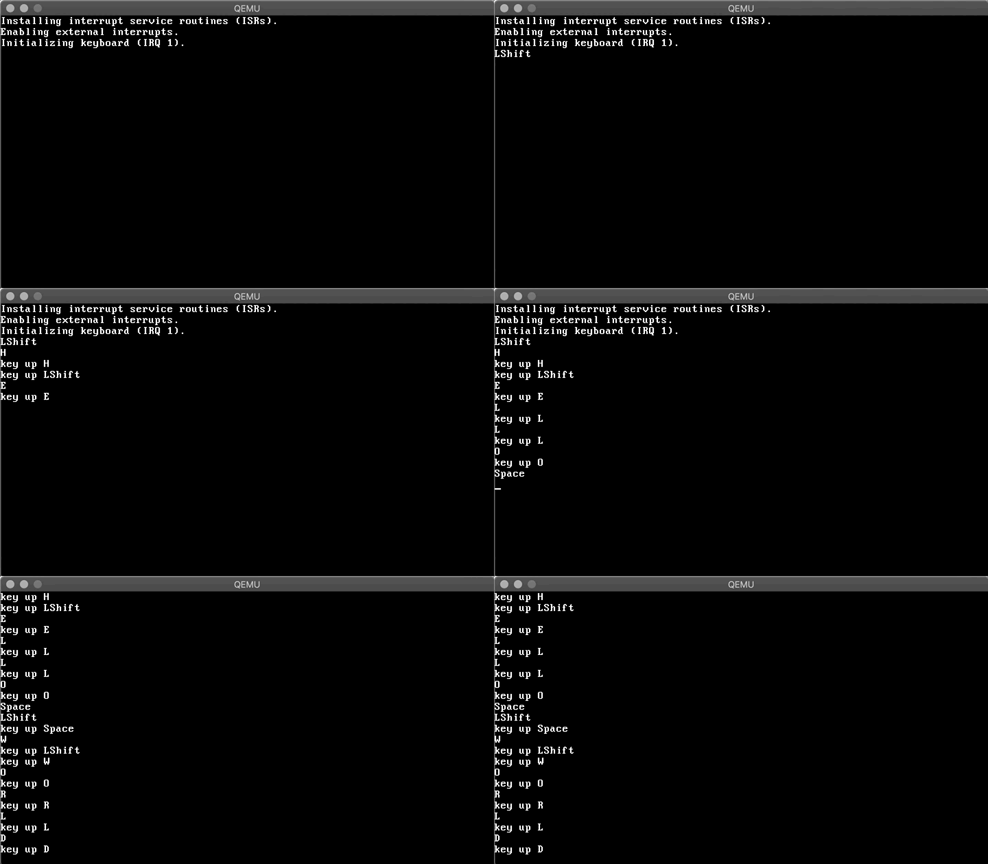
Now let's boot and type something...

demo

Amazing! Having a VGA driver and a keyboard driver in place, we can work on a simple shell in the next post :)

DIY Game Console Using SSD1306 OLED Display and NodeMCU/Arduino UNO

DIY Game Console Using OLED Display and NodeMCU/Arduino UNO Have you ever wondered if you could create your own handheld game console? In th...